


Send Message
Hua'ōlelo pilikino: He mea nui loa kāu pilikino iā mākou.ʻO kā mākou hui pū e hoʻolaha i kāuʻike pilikino i kekahi mauʻaeʻia.
Hoʻohālike No.: NSO4GU3AB
Nā kaʻa: Ocean,Air,Express,Land
ʻO keʻano o ka uku: L/C,T/T,D/A
ʻO Incoterm: FOB,EXW,CIF
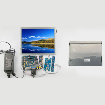
4GB 1600MHZZ 240-PIN DDR3 UDIMM
Hōʻike Hoʻomaopopo
|
Revision No. |
History |
Draft Date |
Remark |
|
1.0 |
Initial Release |
Apr. 2022 |
|
![]()
Ke kauoha nei i ka Papa Pūnaewele
|
Model |
Density |
Speed |
Organization |
Component Composition |
|
NS04GU3AB |
4GB |
1600MHz |
512Mx64bit |
DDR3 256Mx8 *16 |
ʻO ka weheweheʻana
ʻAʻoleʻo Hengstar Ungstar i hāʻawiʻiaʻo DDR3 SDRAM DIMMS (UNBRAFered Double Day Student Dram Dram Drive ʻO NS04Ge3AB kahi 512M x 64-bitʻelua mau pūʻulu o 4GB ddr3-1600 cl11 beite heʻumikumamāhā. Hoʻonohonohoʻia ka spd i ka jeducge maʻamau i ka jed dec3-1600 timing of 11-11-11 ma 1.5v. Loaʻa i kēlā me kēia hola 240-pin dimm i nā manamana lima gula gula. Kuhiʻia ka DEMM i ka DIMM i manaʻoʻia no ka hoʻohanaʻana i ke hoʻomanaʻo nui inā hoʻokomoʻia i nā'ōnaehana e like me nā PC a me nā hana hana.
Nā hiʻohiʻona
ʻO ka Pūnaewele POwer: BDD = 1.5V (1.425V a iʻole 1.575V)
VDDQ = 1.5V (1.425V a i 1,575V)
800mhz Fck no 1600b / pin
programmable casclucy: 11, 10, 10, 8, 8, 7, 6
programkbleleble kūpono loa: 0, cl - 2, a iʻole cl - 1 kaohi
8-bit pre-fetch
BURST lōʻihi: 8 (interleave me ka palenaʻole, stequential me ka hoʻomakaʻana o ka leka uila a iʻole e kākau i ka lele. 4
bi-kuhikuhi i kaʻikepili likeʻole strobe
initers (pilikino) calibration; ʻO ka calibration pilikino ma loko o ZQ PIN (RZQ: 240 Ohm ± 1%)
ONE DEE DETMINANGE me ka hoʻohanaʻana iā Ott Pin
oveird refresh i ka manawa 7.8us ma lalo o nā tcase 85 ° C, 3.9S ma 85 ° C <95 ° C
asynchronous reset
adefatible data-themput Drive ikaika
fly-by topology
PCB: Ke kiʻekiʻe 1.18 "(30mm)
ROHS kūpono a me halgegen-free
Ke kīʻana i nā pākuʻi
|
MT/s |
tRCD(ns) |
tRP(ns) |
tRC(ns) |
CL-tRCD-tRP |
|
DDR3-1600 |
13.125 |
13.125 |
48.125 |
2011/11/11 |
Hale Kūʻai
|
Configuration |
Refresh count |
Row address |
Device bank address |
Device configuration |
Column Address |
Module rank address |
|
4GB |
8K |
32K A[14:0] |
8 BA[2:0] |
2Gb (256 Meg x 8) |
1K A[9:0] |
2 S#[1:0] |
Nā wehewehe PIN
|
Symbol |
Type |
Description |
|
Ax |
Input |
Address inputs: Provide the row address for ACTIVE commands, and the column |
|
BAx |
Input |
Bank address inputs: Define the device bank to which an ACTIVE, READ, WRITE, or |
|
CKx, |
Input |
Clock: Differential clock inputs. All control, command, and address input signals are |
|
CKEx |
Input |
Clock enable: Enables (registered HIGH) and disables (registered LOW) internal circuitry |
|
DMx |
Input |
Data mask (x8 devices only): DM is an input mask signal for write data. Input data is |
|
ODTx |
Input |
On-die termination: Enables (registered HIGH) and disables (registered LOW) |
|
Par_In |
Input |
Parity input: Parity bit for Ax, RAS#, CAS#, and WE#. |
|
RAS#, |
Input |
Command inputs: RAS#, CAS#, and WE# (along with S#) define the command being |
|
RESET# |
Input |
Reset: RESET# is an active LOW asychronous input that is connected to each DRAM and |
|
Sx# |
Input |
Chip select: Enables (registered LOW) and disables (registered HIGH) the command |
|
SAx |
Input |
Serial address inputs: Used to configure the temperature sensor/SPD EEPROM address |
|
SCL |
Input |
Serial |
|
CBx |
I/O |
Check bits: Used for system error detection and correction. |
|
DQx |
I/O |
Data input/output: Bidirectional data bus. |
|
DQSx, |
I/O |
Data strobe: Differential data strobes. Output with read data; edge-aligned with read data; |
|
SDA |
I/O |
Serial |
|
TDQSx, |
Output |
Redundant data strobe (x8 devices only): TDQS is enabled/disabled via the LOAD |
|
Err_Out# |
Output (open |
Parity error output: Parity error found on the command and address bus. |
|
EVENT# |
Output (open |
Temperature event: The EVENT# pin is asserted by the temperature sensor when critical |
|
VDD |
Supply |
Power supply: 1.35V (1.283–1.45V) backward-compatible to 1.5V (1.425–1.575V). The |
|
VDDSPD |
Supply |
Temperature sensor/SPD EEPROM power supply: 3.0–3.6V. |
|
VREFCA |
Supply |
Reference voltage: Control, command, and address VDD/2. |
|
VREFDQ |
Supply |
Reference voltage: DQ, DM VDD/2. |
|
VSS |
Supply |
Ground. |
|
VTT |
Supply |
Termination voltage: Used for control, command, and address VDD/2. |
|
NC |
– |
No connect: These pins are not connected on the module. |
|
NF |
– |
No function: These pins are connected within the module, but provide no functionality. |
Nā Palapala : ʻO ka papa inoa PIN ma lalo nei he papa inoa piha o nā mea āpau o nā mea āpau no nā mea āpau o DDR3. ʻO nā papa inoa inoa āpau paha ʻaʻole e kākoʻoʻia ma kēiaʻano. Eʻike i nā papa inoa PIN no kaʻike kiko'ī i kēia module.
Pūnaewele Pūnaewele
4GB, 512mx64 Module (2rank o x8)


Module dimensions
ʻIke mua

ʻIke mua

Nā Helu:
1.Ell dimensions i loko o nā millimeter (iniha); Max / Min a iʻole maʻamau (keʻano) kahi i hōʻikeʻia.
2.Telence ma luna o nā dimensions āpau ± 0.15mm ināʻaʻole i kuhikuhiʻia.
3.ʻO ke kiʻi dimensional no ka hōʻike wale nō.
Nā huahana huahana : ʻO nā lako waiwaiʻo Companyrial


Hua'ōlelo pilikino: He mea nui loa kāu pilikino iā mākou.ʻO kā mākou hui pū e hoʻolaha i kāuʻike pilikino i kekahi mauʻaeʻia.
E hoʻopihapiha i nāʻike hou aku no laila e hiki ke hoʻopili pū meʻoe wikiwiki
Hua'ōlelo pilikino: He mea nui loa kāu pilikino iā mākou.ʻO kā mākou hui pū e hoʻolaha i kāuʻike pilikino i kekahi mauʻaeʻia.